Fit the supplied auxiliary handle
Match the grooved handle and housing button, attach the original handle and verify its snap fit before adjusting the stance.
Version 2.0.0. Required observations are marked *. Your answers stay in this browser.
1. Match the model and parts
Remove the battery. Find LST300 and the adjacent type number on the tool label. Compare the guard, cap, spool and assembly figures with the linked LST300 manual. Use ServiceNet for your exact type if they differ. LST300 is not a bump-feed head.
Region: US
Parts: Automatic-feed head with AF-100 spool; match model and tool type to manual
Not covered: LST420 / LSTE525; GH corded models; Dual-line heads; Metal line or blades; Nonmatching tool type or modified head; Unknown tool type or missing exact-type manual; Bump-feed conversion.
Choose the versions you can confirm.
Compare versions →2. Prepare
Keep the battery removed if the exact type/manual match is unknown or parts differ from the figures. Stop for a damaged battery, exposed wiring, a faulty switch, cracked guard, broken spool/hub, damaged cap tabs or housing slots. Use an authorized service center. Never open the battery, motor housing or charger.
Consumables and fit
| Item | Specification & fit | Do not substitute |
|---|---|---|
| Auxiliary handle if a replacement is needed | Exact LST300 tool-type part from manufacturer support Original documented groove and two-button mounting | Unverified handle, altered grooves, broken housing buttonsEnglish p8 Attaching the auxiliary handle; figs F–H |
3. Follow your checks
Match the model and preparation to start.
Read all possible routes
Is the battery removed, the trigger released and the cutting head stopped, with no battery damage, exposed wiring or faulty switch?
- Yes — Keep the battery removed for every hands-on step.
- No — Stop using the tool for electrical, battery or switch damage. If you have only omitted battery removal, make the tool safe before restarting.
- Not sure — Keep the battery removed. Save your preparation record and check the matching manual before continuing.
Have you matched the label LST300 AND its exact tool type to the official lookup manual and its figures, with the original AF-100 automatic single-line head?
- Yes — Record the label type and matching manual reference in the first step.
- No — An unknown type, unavailable type manual, different figures, bump-feed head or dual-line conversion blocks this procedure. Use manufacturer support to identify the correct instructions.
- Not sure — Keep the battery removed. Save your preparation record and check the matching manual before continuing.
Is this the original supplied handle for initial assembly, with the grooved attachment shown in figs F–H?
- Yes — Use the assembly buttons on both sides of the upper housing.
- No — For an already fitted handle use the adjustment task. Different or damaged handles require exact-type support.
- Not sure — Keep the battery removed. Save your preparation record and check the matching manual before continuing.
Are both housing buttons and the handle attachment points intact?
- Yes — Align the matching grooved surfaces before pressing the handle on.
- No — Do not attach a handle to broken or damaged supports.
- Not sure — Keep the battery removed. Save your preparation record and check the matching manual before continuing.
4. Follow and record
Complete the checks before recording physical work. Follow steps in order.
Record the exact tool and make it safe
Release the trigger, let the head stop, engage the lock-off and remove the battery. Leave it removed throughout hands-on care. Keep fingers away from the sharp cutter on the guard. Read LST300 and the tool type from the label. Open the official model/type lookup and compare its manual and parts figures with your actual guard, single-line head and AF-100 spool. A readable model name alone does not establish the type. If the exact type manual cannot be obtained, or any figure differs, save a preparation record and stop.
Look for: The battery is physically separate from the tool; your label type and matching manual reference are written below.
Manual: Official model/type lookup instructions; type is beside or below the model numberIdentify the assembly features
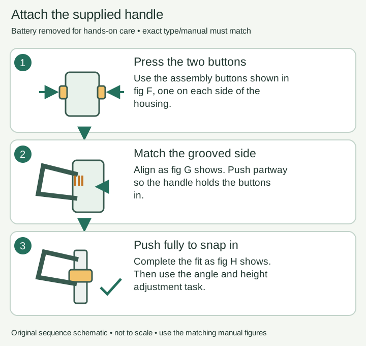
With the tool supported and battery removed, identify the two upper-housing buttons marked 12 in fig F. Compare the grooved handle side with the grooved housing button in fig G.
Look for: The matching grooved sides and both assembly buttons are identifiable.
Manual: English p8 Attaching the auxiliary handle; figs F–HPress the two housing buttons
Press the buttons on both sides of the upper housing as fig F shows. Keep the handle in the orientation pictured in fig G; avoid trapping fingers between the handle and housing.
Look for: Both buttons are depressed and the handle approaches in its matching orientation.
Manual: English p8 Attaching the auxiliary handle; figs F–HStart the handle on the matching grooves
Partially push the handle onto the housing, matching its grooved side to the grooved button. This initial position should hold the buttons in when your hand releases them, as the manual describes.
Look for: The partly fitted handle holds the buttons in without being forced across the grooves.
Manual: English p8 Attaching the auxiliary handle; figs F–HComplete the snap fit
Push the handle fully onto the housing and adjust its position slightly until it snaps into place as fig H shows. If it resists or fails to engage, stop and recheck the matching parts; do not strike or modify them.
Look for: The handle is fully attached and remains held when released.
Manual: English p8 Attaching the auxiliary handle; figs F–HCheck attachment and plan adjustment
Check that the handle stays attached. Use its adjustment button to select an angle, then follow the handle-and-height task for the full working stance. Record the fitting result and keep the battery out until after-care.
Look for: The original handle is retained; height and stance are checked in the linked adjustment task.
Manual: English p8 Attaching the auxiliary handle; figs F–H
5. Keep your result
Record what you observed. A completed checklist does not certify that equipment is repaired.
When to check again
Initial assembly of the original supplied auxiliary handle
Fit during initial assembly; use the separate adjustment task when changing the working stance.
Manufacturer guidance · English p8 Attaching the auxiliary handle; figs F–HSources & fit
- BLACK+DECKER LST300 instruction manual (manufacturer document, retailer-hosted)English p8 Attaching the auxiliary handle; figs F–H · Checked 2026-10-13
- BLACK+DECKER: locate a manual using model and type numberOfficial model/type lookup instructions; type is beside or below the model number · Checked 2026-10-13
- BLACK+DECKER LST300 product and supportLST300 model identity; Automatic Feed Spool; Includes AF-100 · Checked 2026-10-13
Independent, AI-assisted guidance. No physical repair trial is claimed. Manufacturer instructions for your exact version take priority.